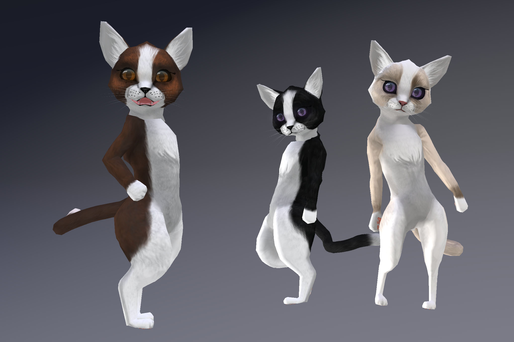
Today, I’m glad to announce that the Kitten avatars are undergoing a long-awaited update, which includes additional Bento functionality plus a brand new animation override. This updated avatar is now available in shop, along with one completely new line – the Bicolour coat pattern!
If you already have one (or more) of either the Tabby or Cheshire avatars and purchased it off the Marketplace, you can expect an automatic delivery for each within the next twenty-four hours. A limited number of recent in-store purchases will also receive this automatic update. If you do not receive your update by Jan 17 2018 (EDT), please see below before contacting me by IM:
If you purchased in-store prior to Christmas and do not recieve an update automatically, please come to the main shop and rez your update token (found in your original Kitten package). There may be a delay but you should still get your update that way. If it times out, please contact me (Aki Shichiroji) directly by IM.
This new bicolour pattern is very much intended to reference the ‘tuxedo’ look that many bi-colour cats have. Five colours are available in this line and these new kittens will include Bento functionality, just like the updated originals!
Changes (2018/01/15):
– Facial and tail Bento support
– New Animation Overrider HUD featuring advanced facial animations specifically for this avatar
– Update system now also uses the blue circle exchanger system (Read the included notecard for full details).
Known issue: RFL Purple Cheshire has not been addressed in this update but will be within the week. Please stay tuned for further info.
Relevant inquiries: Will the applier system used for several other recent releases also be used for the kitten avatar?
– While the possibility is not closed to this, the logistics are non-trivial. The Applier system will not be applied to the kitten avatars at this time.
Will dev-kits and/or clothing be made available for these avatars?
– Both are being taken in to consideration at this time and both are very likely. Again, the logistics of packaging and managing a growing number of coats for this avatar are something that I need to become accustomed to before I will have time to address either. Please IM me to let me know of your interest!
Will animesh support be provided with this avatar?
– It’s a bit early to comment, but animesh for this avatar is quite likely. In all likelihood, Animesh support will involve a customized kit that can be dropped in, but given that these details are rather abstract, the final execution may be somewhat different. There are also some non-mesh and non-rigged components which would need to be converted for use with Animesh should a conversion occur, so I would need to account for the additional time cost for this work.
Stay tuned to the Subscriber Kiosk or the in-world group notices for further news about this or other releases from Wilds of Organica! Join the Subscriber kiosk ( here ) or the in-world group ( here )!
Thank you for your ongoing support!
If you like what you see but don’t think it’s quite right for you, perhaps consider donating to my Patreon? Your continued support helps to produce weekly content (written, modelled, animated or otherwise) and helps to keep original content creation in Second Life!
A small amount of downtime over the past couple of days has given me the opportunity to move forward with my Animesh Willow experiment.
At this point, I have to mention that this is all it is – an experiment. In the course of playing with animating a tree, I ran in to a number of hurdles which I’ll have to consider whether I want to get around before any possible release. (I’ll go in to these a little later).
From the hint that animesh might be a thing, I’d been thinking about using it for more efficient modelling of animated vegetation. Willows are the most obvious candidate for me, since I’ve long avoided creating more.
Original solutions for willows have historically included flexiprims and while these may still prove useful, I wanted to see what I could come up with that wouldn’t be so taxing on the viewer. The opportunity to create something that isn’t so heavily dependant on SL wind is also promising.
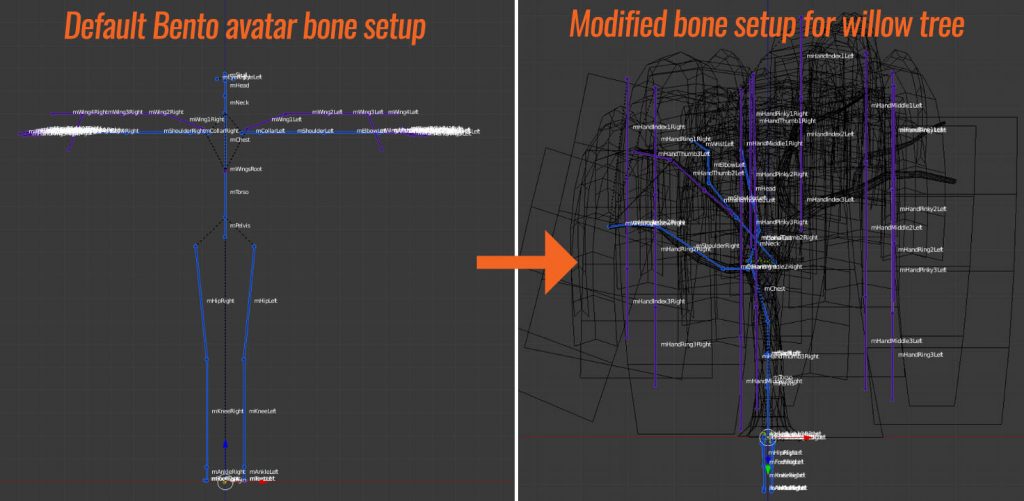
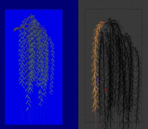
My willow tree armature required some significant modification of the default Bento avatar armature.
Currently, Avastar allows a user to select and move bone joints for either the blue/purple SL armature or green Control Bones in edit mode, then to align them to their counterparts. This is what I did and (so far) I haven’t needed to adjust any of the parenting for this rig.
I opted not to make use of the lower limbs (for now) because doing so can present some orientation issues due to how bones are parented. If i need to in the future, I may put in more time to figure this out, but in this particular use case, I chose to just use the bones from torso up, arms, hands, wings, neck and head (no face), simply because these would handle the geometry sufficiently.
The result is, in a very general sense, positive.
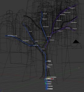
For the most part, the trunk was parented to bones which are logically closer to the middle of the skeleton. So it got torso, chest, collarbones, upper, lower arm, neck, head, etc. Most of the fingers got assigned to equidistant areas around the trunk for foliage.
In hindsight, I would probably rig and model concurrently. Because there was a significant amount of foliage geometry mixed together, selecting appropriate foliage and assigning it to its nearest bone was a bit tedious. Doing this a bit at a time to ensure proper movement would have been the better way to go.
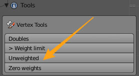
Fortunately, Avastar offers a means of checking for unweighted verts, so this process was made a bit easier as a result.
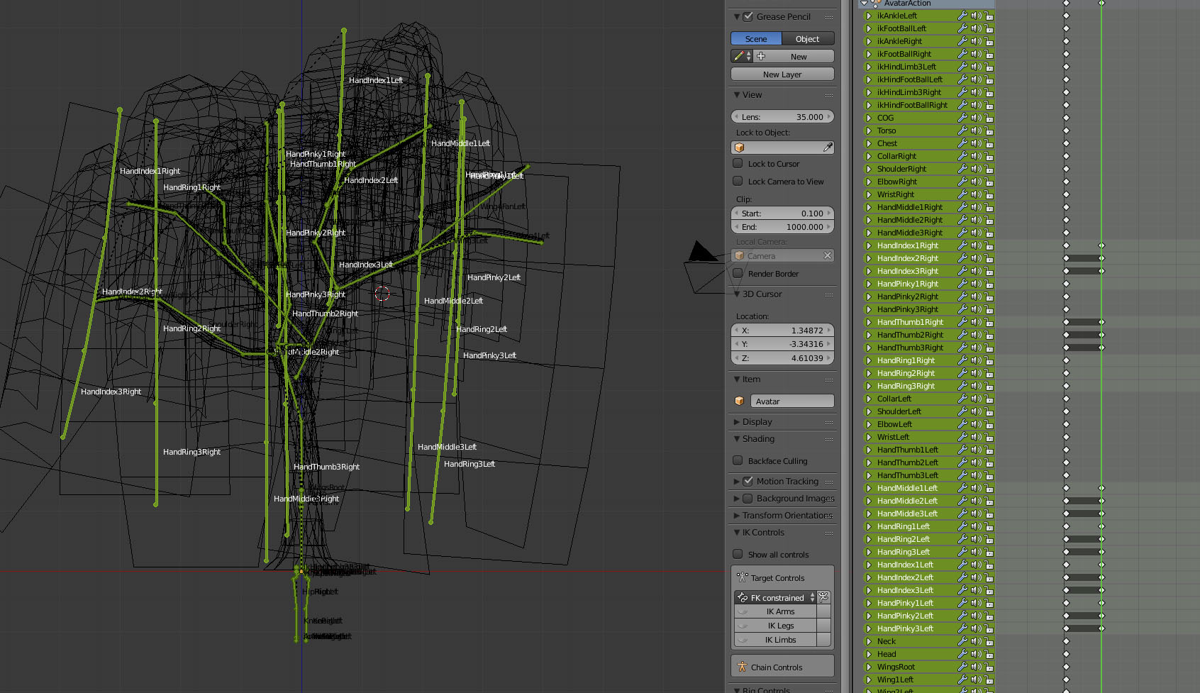
Weighting was undertaken mostly using the weight painting brush, but occasionally I would also hold down Ctrl while making my brush strokes to create a gradient of weights for my selected vertices.
Because there were so many vertices in relatively close proximity, I selected the bones I wanted in weight-painting mode, then hit ‘V’ to show vertices. I then selected the vertices I wanted to paint (rather than painting on everything) and brushed on only the areas highlighted by the selected vertices.
Animating the tree:
Once all of the vertices in the geometry were assigned, it was time to try some basic animation. So far, I’ve just put together a basic sway animation as a test case, but I may continue to create a variety of other animations the tree can play on command.
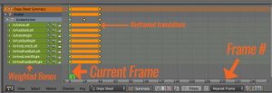
In order to create an animation, I split off a window pane in Blender and switch it to ‘Dope Sheet’ view. This gives me a frame-by-frame listing of bones for which location and/or rotation* has changed, over time (in frames). There are other more detailed and useful views you can use for animation, but this is the most basic view you’ll need right away.
(* Scale changes are ignored by SL, both on the armature and animation side.)
The Dopesheet operates mostly from left to right, although it does list off bones which have been weighted, on the left hand side as ‘channels’. When a bone is selected in 3D view, the appropriate channel will highlight in the Dopesheet view. On the flipside, you can also left-click the name of the bone in Dopesheet view to select the bone in 3D view.
To animate, we need to ‘keyframe’ a set of changes in rotation and/or location and have Blender interpolate these transitions from keyframe to keyframe. In this case, the chief translations we need to make will be rotational.
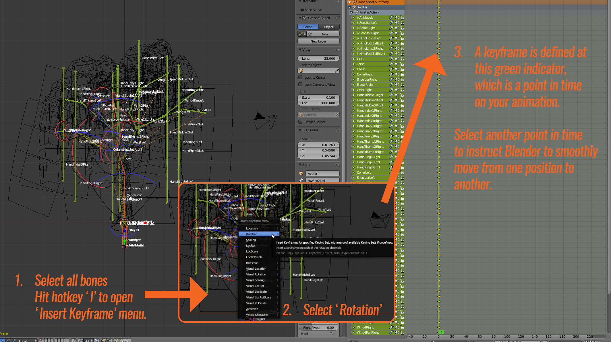
To begin, I select every bone in the armature and keyframe the current rotation as a keyframe (Hotkey I, select ‘Rotation’). This will be my starting frame.
Next, we need to create the second position for the appropriate bones. Since I am only moving the hanging foliage, I select the appropriate bones (mostly just finger bones) and rotate them in the general direction I want.
Then, since I just want to test and loop motion between these two keyframes, I select all of the points from the first keyframe, duplicate them and move them to where I want my end frame to go, allowing the animation to seamlessly move from the last frame to the first when it loops.
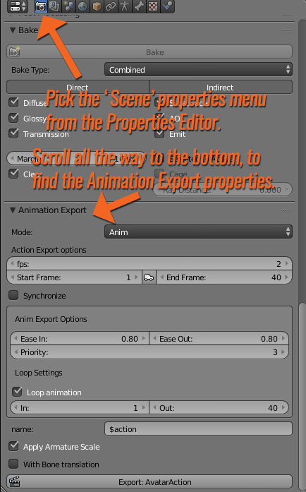
Next, we need to define our export settings to convert these keyframes to a full blown animation that can be used in Second Life.
Of note: Normally, frames per second (FPS) is set around 24. This particular animation has been slowed down significantly such that only two frames play per second, for a much more subtle effect. This can be played with depending on application – sometimes I will tinker with this to speed up or slow down walk-loops for avatars.
By default, I export .ANIM files instead of .BVH files – I don’t play much with the system morphs that come with .BVH and in this case, such morphs (system avatar-based facial expressions, hand gestures) are not applicable to this sort of content.
Once I have defined the start and end frame for the animation as well as the start and end frame for the loop (not always the same!), I click ‘Export: AvatarAction’ and save it with an appropriate file name.
In-world, I enable my willow as an ‘Animated Mesh’ object and drop the animation in to the mesh. Some additional scripts are needed to make use of this animation – some sample scripts to get you started can be found on the Animesh regions on ADITI grid currently. Hopefully we’ll see some more sample scripts on the wiki soon too.
The result:
Current downsides:
Animesh currently can’t be resized. They make use of the armature, where the size is defined upon upload. It may be necessary to create several different sizes for variety and, depending on application, special attention to scaled animations may be necessary as well.
Transparent textures placed upon Animesh-enabled geometry currently do not cast a correct shadow.
Base 200LI – this is likely to change for the better. Vir Linden has always maintained that the current 200LI base is boilerplate and mainly intended to be more restrictive than the ultimate release. Once I have a better idea of base cost, I’ll have a better idea of whether I’d like to move ahead with further LOD optimization and more detailed animations.
So for now, this willow will be on my backburner until we have more info from the weekly content creation meetings (Thursdays at 1PM SLT, Animesh 4 region on ADITI grid).
In any case, I wish you all a very Happy New Year!
I’ve had the fortune of being able to pick up more work in the past year and also the opportunity to present my thoughts and new releases with you lately here on the blog – I’m really looking forward to keeping the ball rolling in the coming year and hope to have more to share with you soon!
If you found this or any other of my articles helpful, please consider becoming a Patron! Doing so supports further articles of this kind and my content creation in general. Alternatively, if you like the sorts of things that I make for Second Life, drop by my Marketplace listing or my in-world stores and check out what I have to offer!
Unless otherwise noted, I (Aki Shichiroji) and this blog are not sponsored in any way. My thoughts are my own and not indicative of endorsement by any associated or discussed product/service/company.
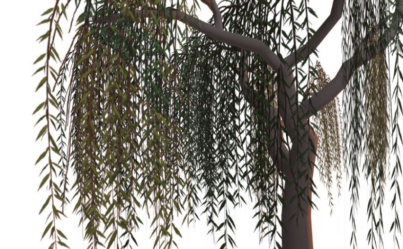
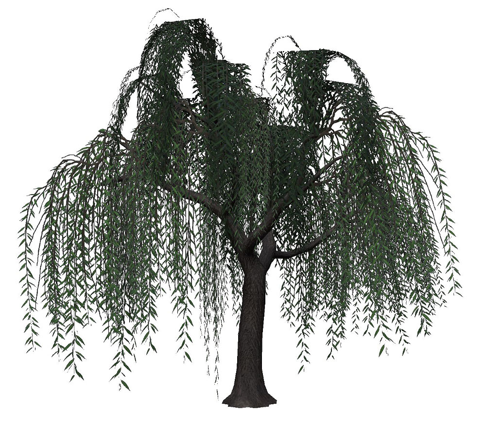
Last time, we left off with the start of some great foliage for our willow tree, but the placement overall was a bit sparse.
Today, we’ll look in to ways of bulking up the foliage so that it looks more healthy.
At this stage, the easiest way to develop a stronger silhouette from all angles is to consider the foliage as multiple pieces of a whole, each varying in size but as a whole ‘mounding’ or ‘padding’ in key areas.
There are a few different techniques available for the tree-making process, but because we’re dealing with a tree that has somewhat out-of-the-ordinary foliage, I’ve chosen to create planes of geometry which have been mapped to parts of a larger texture and to have each of these planes intersect at a common area, to simulate a branch.
Here, I’ve used much the same process as last time to create a variety of different foliage shapes based upon some underlying branch drawings.
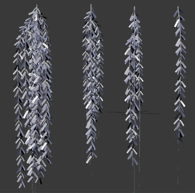
The same leaves and stems we used for the sideways texture are repurposed here, again with the help of bezier curves, which allow for non-destructive manipulation of geometry when a ‘curve’ modifier is added to the mesh object.
A gentle sweeping shape is added to the plane to simulate the slight upward growth, then strong downward plunge of foliage due to gravity. Once I have a shape I’m happy with, the geometry gets duplicated and resized, then I’ll take the geometry and map it to a different strand of foliage within the same UV map for some variety.
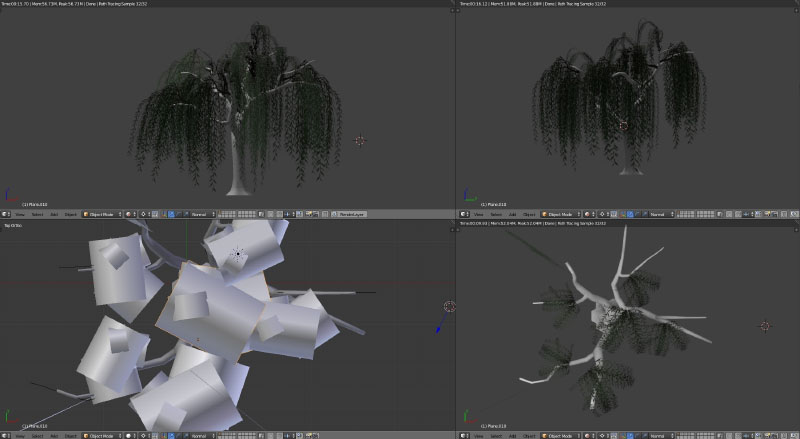
At this point, I split up my 3D view so that one view is using a rendered view and the other is solid or wireframe to properly place each piece so they intersect properly.
Once I have a cluster of this type of foliage that I’m happy with, it gets placed in strategic places where the other foliage type was lacking. It can also be helpful to hide the other foliage material temporarily to aid in clear placement.
It’s important to take multiple angles in to consideration here; while it’s not always possible for an object to look good from all angles, the goal here is to create visual interest through a play between areas where there are foliage and areas where there are not.
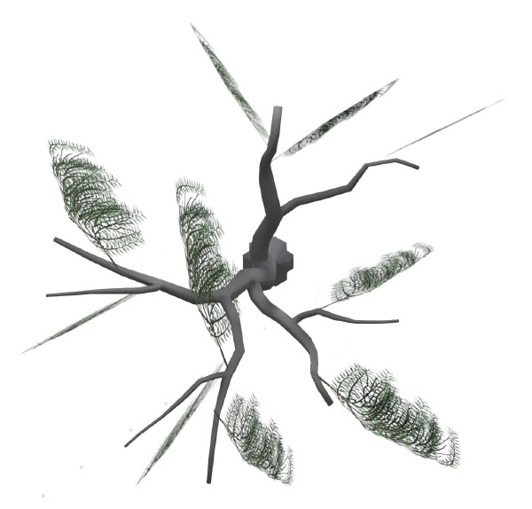
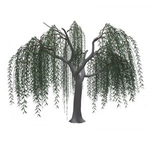
There’s still a ways to go in terms of filling out volume from the top-down view, but progress is being made!
My immediate priority is to create an effective silhouette along the top surface of the tree. Then, I do the same working from a top-down view, taking care to create leaf cover in trunk/branch areas which are still bare.
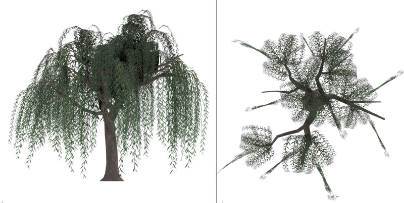
It’s during this stage that some experimentation in balancing the different foliage geometry shapes is important. I started out using a variety of upright planes to create the impression of volume from the front view, but adding rounded foliage makes a big difference! There’s still a lot of push and pull to go, but this has come a long way compared to the tree we were left with by the end of last week’s post.
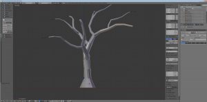
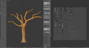
Also, you might notice that I got around to texturing the trunk; this was accomplished by importing a .OBJ copy of the trunk to Substance Painter and working with the tools therein.
I usually start with a base wood material, but never leave it as is. For one thing, Substance Painter still isn’t smart enough to figure out how to hide seams, and for another, I like to add a lot of little touches to make the look a little more unique.
In this case, I created another layer overtop of the wood and used a scratchy brush to create the deep furrows this tree’s bark tends to have. The brush included both a diffuse and height element so that I could give the impression of accumulated dirt and shadow, paying particular attention to seams and minimizing the tonal differences in these areas.
I then also made use of a particle brush to blow some dust and grime all over to add a bit more age and wear to the texture.
These textures were then exported using my usual PBR SpecGloss configuration (the default preset in the exporter) and added back to the model in Blender for one more rendering pass, since I wanted just a bit more kick than the plain textures would provide, given SL’s existing material shaders (somewhat limited).
Moving forward, I’m likely to do a bit more balancing of foliage to make it a bit more subtle, but the basics are there.
Next week, I hope to have enough time to experiment with rigging & animations, plus consider the feasibility under current testing conditions.
If you found this or any other of my articles helpful, please consider becoming a Patron! Doing so supports further articles of this kind and my content creation in general. Alternatively, if you like the sorts of things that I make for Second Life, drop by my Marketplace listing or my in-world stores and check out what I have to offer!
Unless otherwise noted, I (Aki Shichiroji) and this blog are not sponsored in any way. My thoughts are my own and not indicative of endorsement by any associated or discussed product/service/company.
Today, I figured I’d touch on my process for creating textures.
While many folks prefer to use a photograph for their texture, I’ve always worked from scratch, creating my own textures digitally, while referencing a large number of photographs for ideas and clues about growth habit.
With respect to trees, I usually start with a few variations on a base leaf, taking care to work out the base silhouette.
In the case of weeping willows, the leaves are narrow,oblong, and taper gradually. While the final product will ultimately be much smaller and not show small details like serrated edges, I usually add them anyway, along with veins so that these elements can give hints of themselves later.
It’s usually a good idea to create a variety of different leaves, even if they are a slight modification of one base shape. This allows the final branch texture to have some variation to it, even if, at a distance, the differences are small.
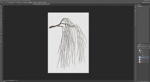
Sometimes, the use of traditional media for texturing is helpful too. I have used my share of drawing tablets but (even considering the use of Cintiq tablets) none of them can truly replicate the intuitiveness of simply taking pen or pencil to paper and simply drawing. Sometimes, it’s just easier to sketch out a base to work from, clean it up or paint over it, rather than drawing and erasing ad nauseum via tablet, and this is what I’ve done here.
This and some other branches were drawn with pencil, scanned, cleaned up and painted over. Using this process, I was able to put together a sideways branch, which is now at a prime stage for the addition of leaves in Blender.
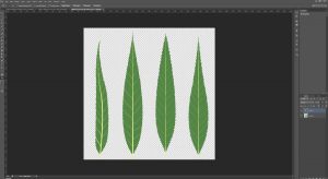
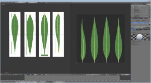
I usually start by unwrapping the UV of a plane to fill the whole area of a UV layout matching the proportions of my leaf texture. In the Node Editor, this object gets assigned a material with the leaf texture as a diffuse map. I additionally assign transparency to the material, using transparency from the texture to be the deciding factor in what gets rendered.
The plane gets cut up so that each piece of geometry gets a different leaf. I then also bring in the branch texture and put it on a vertical plane object (using a similar node setup as above) by adding it to my Diffuse Map node in the Node Editor.
Once this is in place, I divide the Blender windows such that I can view a preview in Render mode on one side as well as edit in either Texture or Wireframe mode on the other. This allows me to move leaf textures to match the branch texture relatively quickly, while still seeing the results (and how the transparent textures interact with each other) in real-time.
In this case, leaf geometry was laid out and duplicated with an Array modifier and also given a curve modifier, so that the geometry would conform to an extruded curve (to act as a stem). This allowed me to move and deform the long string of leaves in any way I wanted.
Special consideration is made to maintain variation and depth. Being able to use a 3D program to put together this texture means that I can take the time to create parts of the foliage which move forward or recede. Setting my texture workflow up this way also means it would be easy to replace the leaf texture later for other texture sets (fall colours, for example).
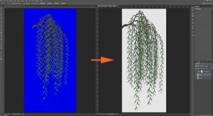
Once I have an arrangement I’m happy with, I add a solid emissive blue background, set up some appropriate lighting, position the camera and take a render (F12) of the camera view.
The result gets saved and opened in Photoshop. I select as much blue as possible, then delete it from the layer, leaving behind a transparent background. I then add a Hue/Saturation adjustment layer and de-saturate any remaining blue colour on the preceding layer.
Any additional cleanup should be done to the texture at this stage. I save a .PSD file as well as a .PNG at full size, then I repeat the placement process for branches along the full trunk. Once I have finalized placement, the file gets saved again as a .TGA, with an appropriate background & alpha channel and at a more SL-appropriate image size.
There can be a lot of experimentation at this stage and the solution, for trees, isn’t always a flat billboarded texture. As it stands, this tree still looks a little spare!
In my next article, I’ll show what additional geometry and texture work goes in to making the tree look believable from multiple angles.
If you found this or any other of my articles helpful, please consider becoming a Patron! Doing so supports further articles of this kind and my content creation in general. Alternatively, if you like the sorts of things that I make for Second Life, drop by my Marketplace listing or my in-world stores and check out what I have to offer!
Unless otherwise noted, I (Aki Shichiroji) and this blog are not sponsored in any way. My thoughts are my own and not indicative of endorsement by any associated or discussed product/service/company.
Family is up from the States this week, so there was a family dinner. I also took a bit of free time earlier today to pick up a lovely vintage table for my kitchen, which is sorely lacking in the style department.
I am overseeing and creating content for a couple of new work projects and hope to be able to talk more about them soon – in the mean time, I figured I’d touch a bit on some work in progress I’ve got in mind for an upcoming Organica release.
It’s been a *long* while since Organica offered a weeping willow. Simply put, it’s mainly because I am not real big on flexi prims being linked in to mesh and, back when I did make some, we only had alpha blending (and not masking) – so it would be common to run in to issues where some textures would overlay others in an undesirable fashion.
With those caveats in mind, I figure it’s a good time to revisit willows, because let’s face it – a naturally moving tree would be a great example of non-animal Animesh.
While I won’t touch on the rigging just yet here, I will at this point discuss my general modelling & UV layout process.
The process begins with a simple cylinder – usually with no more than 12 sides, and with the length divided a multitude of times. I usually create the UV layout for this cylinder pretty early on (even though I do later unwrap the geometry again) because multiple copies will be made of this cylinder and it’d be nice not to define seams for each and every one.
While I could probably define the shape of the geometry by moving the verts around, lately I’ve taken to adding a Bezier Curve nearby and applying the curve as a modifier to the cylinder, taking care to apply scale and location before any heavy modification takes place.
By using a modifier, non-destructive changes can be made, allowing for a considerable amount of experimentation in placement and rotation prior to committing to a final shape. In this case, I am moving various nodes in the bezier curve to direct the overall direction of the mesh.
How does one use Bezier curves?
Assuming you are already familiar with how to move, rotate, scale and extrude vertices, edges and faces in geometry, Bezier curve nodes are similar to individual vertices (although more accurately, they are very similar to NURBS nodes).
A Bezier Curve in Blender (in object mode on left, edit mode on right)
Basically, each node along a curve is accompanied by a pair of handles which control the direction of the curve directly before and after the node. They are always 180 degrees from each other. The closer these handles are to the node, the shorter the area of influence they will have.
The default bezier curve will give you two nodes. You can add nodes in between by dividing the space between the two in the same manner as you would between two vertices. You can also extrude additional nodes from the start or end of the curve.
You can either apply this curve to existing geometry (using the ‘Curve’ modifier’) or extrude some basic geometry along the curve (using the ‘Curve’ properties menu, when the curve is selected). There are some additional advanced things you can do to this extruded geometry (such as non-destructive tapering or bevelling) but for the purposes of this demo, I have only applied my curves to geometry as a modifier.
It should be noted at this point that, even at top level geometry, I do not subdivide at this point. This is important, since fixes will later be necessary to clean up the results of proceeding workflow. It’s way less hassle to redirect and merge fewer vertices than more. If smoother, more curvaceous transitions are needed, subdivisions should occur after the final UV layout has been finalized (IE: not now!)
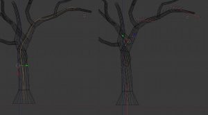
After the trunk has been defined, I select both the mesh and the curve and duplicate them at the same time, adjusting basic position, scaling and rotation at the Object level, then editing individual branches for variety by selecting the appropriate curve and editing in edit mode.
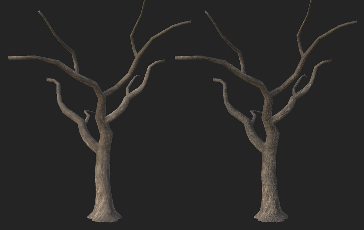
After I am satisfied with all the branch placement, I join each branch to the main trunk using a Boolean Modifier (‘union’ setting) to create the branch geometry in the same object as the trunk and also to join it with the trunk. This leaves behind a copy of the original branch, which can either be archived to a different layer or deleted entirely.
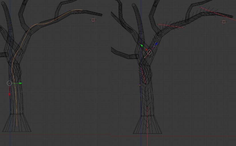
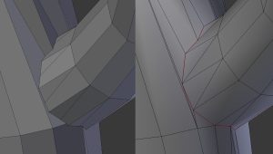
I do this for all of the branches, then go back and check each of the joints between the branches and trunk.
Before (left) and after (right) some vert cleanup at the branch/trunk joint. Also, seam assignment.
Typically, use of the boolean modifier will create extraneous verts, showing the point at which each face intersected with its adjacent geometry. This is, by and large, undesirable and I will usually either merge several extraneous verts to converge on one desired vert OR i’ll select edge loops and slide them in the correct direction, taking care later to remove any remaining duplicate vertices. Checking for N-gons (polygons with more than 4 edges) should also be done at this stage.
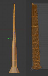
Cleanup is done around each joint, after which I attempt another UV unwrap to achieve a nice layout that is fairly clean, not overly stretchy, correctly scaled and laid out in a convenient direction.
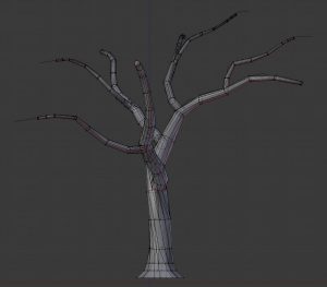
Tree trunk & branch UV layout
The overall silhouette and UV layout have been achieved. Further modifications within these constraints (additional edge loops to create more curves, for example) would be ideal at this point.
We’ll leave it here for now. Next week, I’ll discuss foliage geometry, layout and general texture creation.
Did you know I have a Patreon account? If you enjoy this content, please consider becoming a Patron! It helps me create more like it and offers a variety of rewards. Alternatively, if you like the sorts of things that I make for Second Life, drop by my Marketplace listing or my in-world stores and check out what I have to offer!
Unless otherwise noted, I (Aki Shichiroji) and this blog are not sponsored in any way. My thoughts are my own and not indicative of endorsement by any associated or discussed product/service/company.
As promised, a number of other new items are now also available this week (thru Dec 1!) at Candy Fair!
Alongside the Cat Ears & Tails, there will also be the following:
Much like the Cat Ears & Tails, these Bento attachments come with the short ear & long tail AO, which is intended for layering over existing human AO animations. They come with lifetime updates and are optimized for use with viewers which use the Advanced Lighting Model. They are mod, copy, no transfer , with some no-mod scripts.
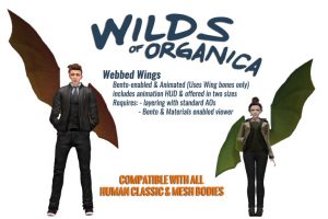
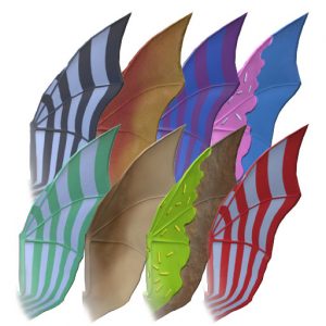
This Candy Fair edition of webbed wings is much like the original release, in that it includes both small and large mesh, as well as AO, for various body shapes. They come with lifetime updates and are optimized for use with viewers which use the Advanced Lighting Model. These, too, are mod, copy, no transfer, with some no-mod scripts.
You can pick up the Cat Ears & Tail, Mouse Ears & Tail & Candy Fair Edition Webbed Wings at Candy Fair here until December 1! (Some previous years’ Candy Fair gacha releases are also available again at the Gacha Gardens there too!)
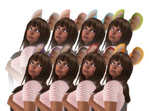
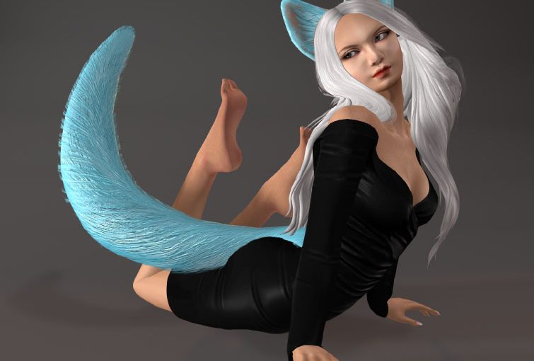
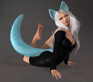
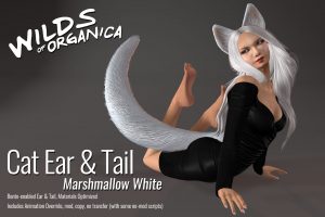
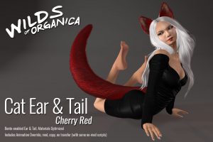
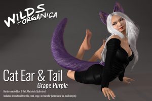
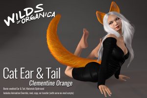
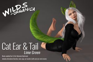
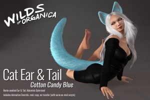
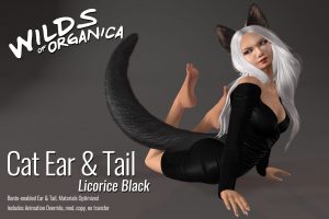
A few new items are in the works for Wilds of Organica’s debut at Candy Faire (previous years it was Organica Specialty Landscaping & Decor) – What I can talk about so far includes this new Ear and Tail release for those who appreciate the feline persuasion!These Bento-enabled and animated attachments take advantage of advanced materials to produce a realistic fluffy and furry texture.
Eight treat-themed colours are available and these attachments come with an AO HUD for layering over top normal human animations! (Please note – does not come with its own human anims).
Other items are also in the works, time permitting, but this is what I can talk about so far.
Candy Faire opens on November 17 and runs thru December 1st! This and other products will be exclusively available there during the event! (They’ll hit the main store and Marketplace afterward) Further info on this next week!
Did you know I have a Patreon account? If you enjoy this content, please consider becoming a Patron! It helps me create more like it and offers a variety of rewards. Alternatively, if you like the sorts of things that I make for Second Life, drop by my Marketplace listing or my in-world stores and check out what I have to offer!
Unless otherwise noted, I (Aki Shichiroji) and this blog are not sponsored in any way. My thoughts are my own and not indicative of endorsement by any associated or discussed product/service/company.
This week has been a bit of a mish-mash from a work perspective – not only is Candy Faire coming up but we’ve gotten a major go-ahead with a work project, as well as some additional requests that I’ll touch on later this month.
Today, I figured I’d discuss some techniques with regard to texture maps and how they can provide additional detail to your work.
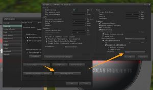
The Advanced Lighting Model has been a part of the SL viewer for around five years, yet at this stage it’s still quite seldom that current content creators make use of it to its greatest extent.
There is a common misconception that the Advanced Lighting Model is only usable if you can view shadows and projectors, but that’s not actually the case. The option to turn off shadows and projectors may be in a different spot depending on which viewer you use, but on the mainstream viewer, it’s located here:
So with that addressed, how can Advanced Lighting Model help us?
As I touched on during the last article, a major part of making more efficient content is finding ways to add detail without adding costly geometry, and a large part of that has to do with the texture map options provided by the ALM functionality.
What do all these texture maps do?
Diffuse (Texture tab)
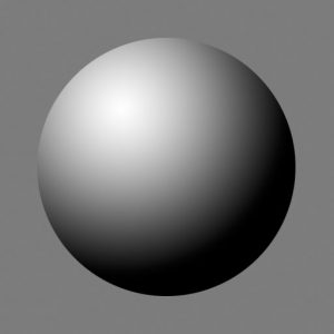
Diffuse maps are the basic textures we use to give objects their flat colour. On their own, they do not provide any effect with regard to how shiny or bumpy an object may be, instead offering only a means to see colour on the object under diffuse lighting conditions (IE: no reflections or projections).
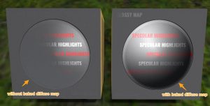
Diffuse grey colour with no baked detailIn-World GIF. Click to animate!
We might sometimes ‘bake in’ more details to a diffuse texture, but it’s important to note that these details will be static and not change with differing light conditions.
In-world GIF! Click to Animate. Notice how the white highlight doesn’t change?
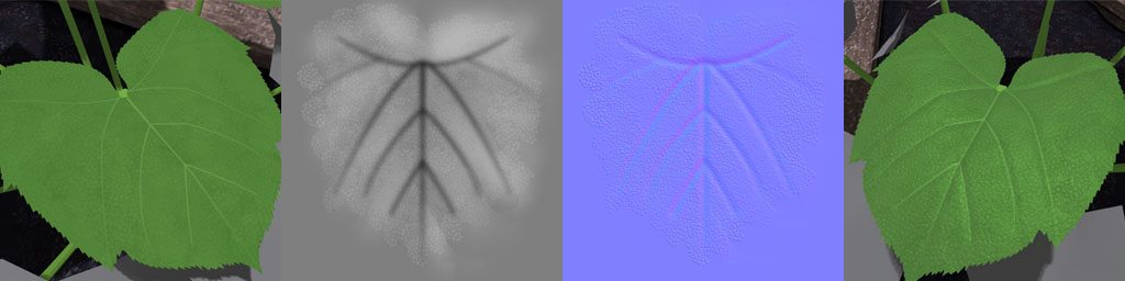
Normal maps (Bumpiness tab)
In SL, the Bumpiness tab uses ‘Normal’ maps, which tell the camera which angle each pixel should face and to what degree these pixels should recede or protrude. This shouldn’t be confused with bump or height maps, which use the monochrome spectrum to define distance of a given pixel from the camera – SL does use these to some degree, but not for the same purpose as one might expect.
Height maps become more commonly used when it comes to applications in SL where a strict height difference (and lack of angle info) is used – IE: Height maps for full regions – but I won’t be going in to that today.
A spherical normal mapIn-world GIF – click to animate!
Under the right circumstances, a normal map can make a big difference between a flat plane and a flat plane with rounded buttons. Most commonly, the addition of normals is most noticeable when combined with Shiny maps.
Shininess (Specular)
Shiny maps are a combination of two different types of maps – Specular and Glossiness maps.
Specular maps control how much light gets bounced back from an object’s surface, as well as what colour that light would be. Glossy maps control how shiny or matte something is.
Combined, Glossy and Specular maps can control how matte or shiny something is as well as how diffuse or sharp the reflected highlight will be.
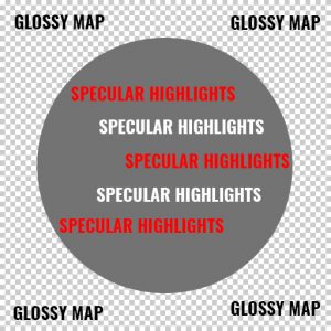
Shiny maps are gloss and spec maps combined! Click to see this animated & notice the glossy ‘gloss map’ lettering and sphere.
Adding Material maps to your workflow:
Creating your own bump/height maps using a graphics editor:
Height/Bump maps are created in greyscale. Of note, it is typically not enough to simply convert your diffuse texture to black & white, as not all lighter details on your diffuse texture are necessarily supposed to be closer to the camera, nor darker details necessarily supposed to be farther from the camera.
Not all lighter details on your diffuse texture are necessarily supposed to be closer to the camera, nor darker details necessarily supposed to be farther from the camera. As such, plainly converting a diffuse texture to a height or normal map without any changes isn’t always the best solution.
I usually start with 50% grey as a background layer, then use additional layers to create depth. Anything I want to recede gets a darker shade. Anything I want to come forward gets a lighter one.
Areas of higher contrast will see sharper bumps. Areas of lower contrast will be more subtle.
But Aki! You just got done telling us we usually don’t use height maps on objects!
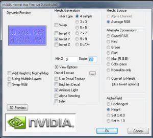
While I did mention Normal maps are more commonly used within Second Life, the truth is most Normal maps are acquired by creating a height or bump-map, then having a program convert it for you.
Just follow the installation instructions and you’ll find it under Filters in Photoshop the next time you load the program up. In it, you can control the scale of your normal map’s height, sample granularity and more, but usually those two (height and granularity) are all that I change.
Alternatively, there are a fair number of web-based converters with varying degrees of customization. Notably:
There are a variety of additional programs that will do conversions for you, usually (but not always) bundled in with other functionality.
Crazybump – offers a variety of licenses depending on use. For selling in SL, expect to purchase the professional license.
Quixel Suite – offers a variety of licenses depending on use. For selling in SL, an Indie license is usually sufficient. Of note, this suite includes nDo (which is the Normal generation component), dDo (which permits application of high detail scanned materials) and recently 3Do (which is a baking utility.) Each of these can be purchased separately.
Substance Painter – This is a pretty commonly used standalone program amongst SL creators these days. It allows similar functionality to Quixel’s dDo, but also offers more in-depth painting-style application, along with procedural and particle brushes. If you have already created some height/bump maps, you can still use this to export Normal maps too! Content creators making under US$100K can safely use the indie license.
Creating your own bump/height maps using a modelling program:
I mostly just use Blender or ZBrush, but I’m including a series of videos that go through normal creation using the big four modellers used for SL content creation below.
All of these methods assume that you have a higher-poly version of your low-poly model and that your low-poly model has already been assigned a UV layout:
Creating your own shiny maps using a graphics editor:
Much like creating Height/bump maps, both Specular and Glossy maps can be created with your favourite graphics editor or with a variety of other programs (Quixel Suite, Substance Painter). Most of these other programs will give you the appropriate separate maps when exporting ‘PBR’ materials – that is, Physics Based Rendering – but you’ll have to combine the specular and glossy maps in your graphic program later if you would like some variance in the matte/glossiness of the object.
A specular map, without any glossy channel applied.Specular map only, applied to the grey diffuse texture – notice how the surface is uniformly glossy? Click for animation.
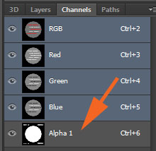
In my own work, the glossy map is applied to the specular map as an alpha channel. Any areas on the alpha channel that are black will mask off the reflectiveness of the object.
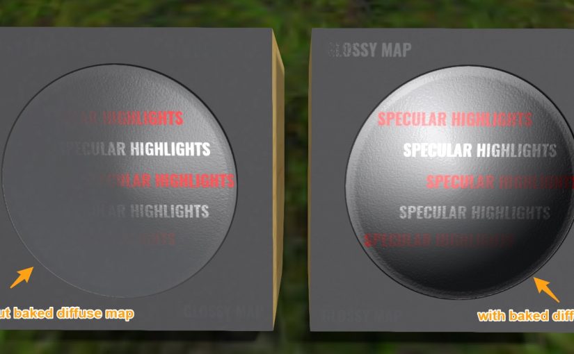
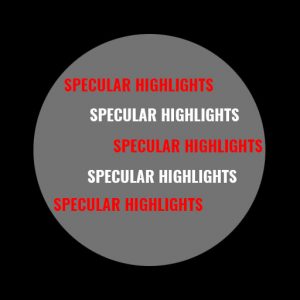
A shiny map – includes both specular highlights (inside the circle) and glossy elements (opaque vs transparent elements)With the glossy alpha channel added to the specular map, we now have a shiny map. Notice how certain parts of the surface are now matte? (Click to animate)
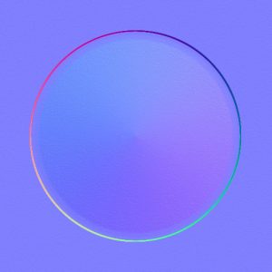
What does this all end up looking like?
Finally, here’s what all of these texture maps look like, put together.
With the normal map added, the circle now has a bit more dimensionality. We are also able to see how specular highlights become less noticable as the camera moves away from them face-on.
If we add back that simple baked shadow texture from above, we can give this surface even more depth!
Together, these texture maps have extensive application. You can add iridescence to a Christmas tree ornament, for example, or texture to an elephant’s skin. You can add droplets of water to a leaf or provide a scaly sheen to a dragon’s hide.
Hopefully this provides a good starting-off point for your creations – I’d love to see what you come up with! If you have any questions, please feel free to give me a shout in-world on my main account (Aki Shichiroji) and I’ll be happy to provide feedback or help as necessary.
Hopefully I’ll have more to discuss release-wise, since Candy Faire is imminent! Additionally, there are some other Organica releases in the pipeline. See you next week!
Did you know I have a Patreon account? If you enjoy this content, please consider becoming a Patron! It helps me create more like it and offers a variety of rewards. Alternatively, if you like the sorts of things that I make for Second Life, drop by my Marketplace listing or my in-world stores and check out what I have to offer!
Unless otherwise noted, I (Aki Shichiroji) and this blog are not sponsored in any way. My thoughts are my own and not indicative of endorsement by any associated or discussed product/service/company.
There has been a lot of talk, recently, with regard to what is and isn’t possible within the platform when it comes to content creation and detail. We see this complaint come up commonly with all content, but more recently this has become more of a touchy issue with the coming of Animesh (animated mesh) objects, which are currently being tested on the Beta grid.
As things go, Animesh is currently limited to 20Ktris per linkset, which means that content creators have to be very cautious about the complexity of the models they intend to use.
The most immediate use case being presented are full scale animated NPCs based on existing mesh content (bodies, clothing, hair). Additional use cases include accessorizing of rezzable pets, customization of vehicles, and more.
However, the efficacy of Animesh in terms of accomplishing those goals is questionable.
As things stand, the current limitations (20KTris per linkset, minimum 200LI cost for animated mesh objects) are deliberately conservative so as to accurately assess graphic and server load under heavy use. These limitations are likely to change, but some of the suggestions as far as to what degree have been quite far-ranging. At recent user group meetings, we’ve seen suggestions anywhere from 100-500KTris per linkset so as to accommodate clothing, hair and body mesh.
This might not seem like a lot but for the moment let’s argue that the average fashionista might themselves average between 250-800Ktri range. Today in SL, this is only just manageable in a room with multiple such avatars because we can now elect to filter out performance-heavy individuals by using Avatar Complexity filters. (If you frequently allow your viewer not to do this, chances are you spend a fair amount on a new video card every couple of years. Not everyone can afford that!)
There is no immediate indication that we will have any similar functionality with Animesh. Apart from the polycount restriction and LI, there is also no immediate restriction on how many animesh can be drawn by your camera. As such, placing multiple such linksets in a given area may well create a negative experience for a large portion of the SL userbase, who may not have the most up to date equipment for enjoying Second Life.
It begs the question of content creators – Notwithstanding any easement of these restrictions, what can we as content creators do to create more efficient models for use as Animesh (or even for daily use on our own avatars)?
Design with efficiency in mind.
There are many workflows out there. Some of us are working with Blender, Maya, 3DSMax, SketchUp, ZBrush or even Marvelous Designer.
I am hesitant to point out any one workflow as being ‘bad’, but frankly some of these workflows are designed for higher-detail applications and not for immediate use in gaming.
Does this mean I think they shouldn’t be used?
Not at all, however it’s important for content creators to understand what kind of issues they are introducing to the viewer experience when they present un-optimized content to the consumer market, what the repercussions may be and how to mitigate them.
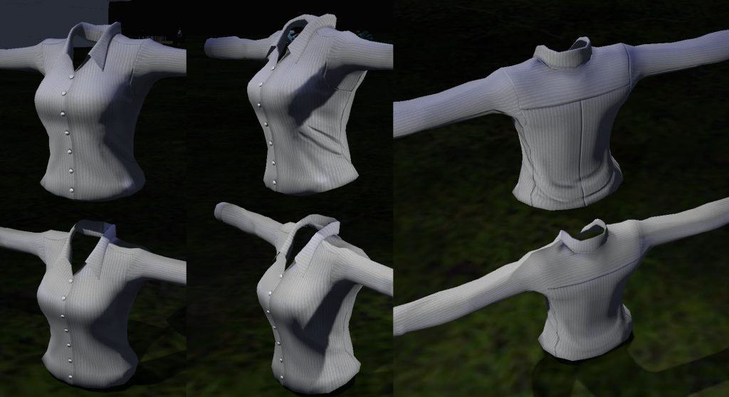
For example, Marvelous Designer allows designers to create garments based on traditional patterning and to see how those garments will fall on an avatar, but even with the recent addition of its quadrangulate functionality, it produces mesh with counter-intuitive edge flow. Additionally, the common practice with MD is to simply export a high-poly mesh to include fine details and call it a day, without regard to how that might impact the viewer in SL.
We have similar problems with ZBrush, which can handle millions of vertices at a time and which does have a means of retopology (making something less complex), but which still requires a lot of tweaking to create something with good enough edgeflow to work well in lower poly situations.
You can work from low-poly to high or high-poly to low based on your preference, but it should be noted that the average avatar doesn’t actually *need* Pixar-level graphic fidelity in their everyday SL experience.
Most people think this wyvern comes out to around 50KTri or more – in actuality, with the use of normal maps, it is far far less (at 14KTri), and the final product may even be less depending on final refinements.
Rather than importing garments to SL with every possible nook and cranny modelled in geometry, designers can (and should) make use of the tools afforded them by advanced materials! This can be done by baking down some of the details from their higher-poly models to diffuse maps but also by creating normal and specular maps that will take advantage of textures instead of geometry to create detail.
Normal maps can make a huge difference when it comes to conveying details! This blouse is under 4KTri,, animates cleanly and still has subtle seam and cloth fold information which some would otherwise model out in geometry.
With this sort of workflow in mind, a 20KTri blouse could easily be reduced to 4-5KTri with minimal detail loss.
Even more savings can be had if animesh are designed and modelled with these restrictions in mind, rather than cobbled together from multiple sources.
With a custom designed animesh human, for example, there is no need to include a full mesh body – only those parts which are visible need be included. Clothing, hair, accessories – all of these can be developed with efficiency in mind to fit the criteria for Animesh limits.
Level of Detail models are also helpful with reducing viewer load at a distance, given the fact that Animesh do not currently become imposters at a distance (even though they express sped up animations just as avatars do).
Balance
Of course, it’s helpful not to think of SL purely in terms of efficiency. We could all just wear stick-figures or rez them and call it a day… but if the visual element were removed what would be the point?
Instead, I’d love to see limitations on these resources to encourage both more efficiency as well as stylistic choices that deviate from the norm. There is a vast niche of style that continues to go untapped within the platform and I’d be really interested to see more interesting art styles rather than a constant push towards photo-realism, personally.
An update is now available to the Drider avatar as the result of feedback accumulated over the past week!
After a considerable amount of time spent testing various mesh body demos (both male and female), I was able to ascertain that the vast majority of mesh avatars fit the initial mesh body shape with minimal issue, assuming default male or female body shapes were used. A small number of mesh bodies did not fit this norm (or did not have sufficient alpha granularity). For these, a special version of the avatar mesh was made, featuring a wider and slightly deeper hip area.
There have been additional resources added to the main documentation, including a full list of bodies tested, whether they are compatible and, if so, what the appropriate alpha settings would be.
Additionally, after some feedback regarding attachment points, I was able to go back in to the avatar file and reposition a fair number of attachment points. Attachment points for the front legs should now all match up to their appropriate bones. Wing attachment points now match up with the second set of legs (lowest joint). Hind attachment points now match up with the third set of legs (lowest joint). Tail base and Tail tip were found to not be movable, so tail base fits the top of the right hind leg and tail tip moves to the top of the left hind leg.
Additional testing involved the most ideal attachment point for adding things to the abdomen – For this purpose, I recommend Pelvis. Spine is affected by the position of the torso, groin doesn’t play well with the bones being used for the spider thorax & abdomen.
Please note: One attachment point will give you up to five attachment slots to use at that one point. To use multiple attachments per point, simply ‘add’ instead of ‘wear’.
All vendors and marketplace listings have since been updated – to check if your package is up to date, please check the description field of your avatar’s box. If it predates 2017/10/21, please exchange your avatar at the Wilds of Organica Avatar Exchanger, which is currently located here (but which you can always find a SLURL for in Aki Shichiroji’s profile (under Picks> Gacha Exchange Policy and exchanger location).
Lastly – there have been some inquiries about a dev kit for the drider avatar. There are plans for this, but it is not available at this time. Interested parties should keep an eye on this blog, join the in-world group or the Discord server for announcements regarding applications and availability.